LABORATORIO 2
DESCRIPCIÓN DEL LABORATORIO :
Veremos como controlar a través de Arduino ocho (8) LEDs puestos en una protoboard, encendido cada LED de izquierda a derecha según la posición de un Potenciometro.
MATERIALES UTILIZADOS
(1) Protoboard
(8) Leds
Cable utp
(1) Arduino uno
(1) Potenciometro
DIAGRAMA DEL MONTAJE EN LA PROTOBOARD
DIAGRAMA DEL MONTAJE EN EL CIRCUITO
FOTOS DEL MONTAJE
- // Pines usados del Arduino (2-9)
- int led[MAXLED] = {
- 2,3,4,5,6,7,8,9};
- // Ciclo para activar los ocho pines como salida,
- // y el potenciometro como entrada del Arduino
- void setup() {
- for (int i=0; i<MAXLED; i++)
- {
- pinMode(led[i], OUTPUT);
- }
- pinMode(pot, INPUT);
- }
- // Ciclo con tiempo variable de prendido y apagado controlando
- // su posición según la posición del potenciometro, el cual se
- // cambia su intervalo que era de 10-1023 a un intervalo de 0-7
- void loop() {
- int valor = analogRead(pot);
- int i = map(valor,0,1023,0,7);
- prender(led[i], 100);
- apagar(led[i], 50);
- }
- // Función de prender, coloca el Pin tal en alto (HIGH)
- // en un tiempo t
- void prender(int l,int t) {
- digitalWrite(l, HIGH);
- delay(t);
- }
- // Función de apagar, coloca el Pin tal en bajo (LOW)
- // en un tiempo t
- void apagar(int l,int t) {
- digitalWrite(l, LOW);
- delay(t);
- }
VIDEO DEL FUNCIONAMIENTO
LABORATORIO 3
DESCRIPCIÓN DEL LABORATORIO :
Controlaré a través de Arduino ocho (8) LEDs puestos en una protoboard, haciendo que un LED se mueva en forma continua de izquierda a derecha, mientras por medio de los valores de dos Potenciómetros se controlan los tiempos que el LED permanece encendido y apagado.
MATERIALES UTILIZADOS
(1) Protoboard
(8) Leds
Cable utp
(1) Arduino uno
(2) Potenciometro
DIAGRAMA DEL MONTAJE EN LA PROTOBOARD
DIAGRAMA DEL MONTAJE EN EL CIRCUITO
FOTOS DEL MONTAJE
CODIGO ARDUINO
- const int MAXLED = 8;
- int led[MAXLED] = {2,3,4,5,6,7,8,9};
- int pot1 = A0;
- int pot2 = A1;
- void setup() {
- for (int i=0; i<MAXLED; i++)
- pinMode(led[i], OUTPUT);
- pinMode(pot1, INPUT);
- pinMode(pot2, INPUT);
- }
- void loop() {
- for (int i=0; i<MAXLED; i++) {
- int valorpot1 = analogRead(pot1);
- int valorpot2 = analogRead(pot2);
- prender(led[i], valorpot1);
- apagar(led[i], valorpot2);
- }
- for (int i=MAXLED-2; i>0; i--) {
- int valorpot1 = analogRead(pot1);
- int valorpot2 = analogRead(pot2);
- prender(led[i], valorpot1);
- apagar(led[i], valorpot2);
- }
- void prender(int led, int ms) {
- digitalWrite(led, HIGH);
- delay(ms);
- }
- void apagar(int led, int ms) {
- digitalWrite(led, LOW);
- delay(ms);
- }
VIDEO DEL FUNCIONAMIENTO
LABORATORIO 4
DESCRIPCIÓN DEL LABORATORIO :
Controlaré a través de Arduino ocho (8) LEDs puestos en una protoboard, haciendo que un LED se mueva en forma continua de izquierda a derecha, mientras por medio de una interfaz gráfica en Processing/ControlP5 se controlan los tiempos que el LED permanece encendido y apagado.
Controlaré a través de Arduino ocho (8) LEDs puestos en una protoboard, haciendo que un LED se mueva en forma continua de izquierda a derecha, mientras por medio de una interfaz gráfica en Processing/ControlP5 se controlan los tiempos que el LED permanece encendido y apagado.
MATERIALES UTILIZADOS
(1) Protoboard
(8) Leds
Cable utp
(1) Arduino uno
DIAGRAMA DEL MONTAJE EN LA PROTOBOARD
DIAGRAMA DEL MONTAJE EN EL CIRCUITO
FOTOS DEL MONTAJE
CODIGO ARDUINO
- #define MAXLED 8
- int led [MAXLED]={2,3,4,5,6,7,8,9};
- int valor=0;
- int i=0;
- int t_on=500;
- int t_off=100;
- int inc=1;
- void setup(){
- Serial.begin(9600);
- for (int i=0; i<MAXLED; i++){
- pinMode(led[i], OUTPUT);
- }
- }
- void loop() {
- if (Serial.available()>0){
- valor=Serial.read();
- if(valor=='t')
- t_on=Serial.parseInt();
- if(valor=='q')
- t_off=Serial.parseInt();
- }
- on(led[i], t_on);
- off(led[i], t_off);
- i+=inc;
- if (i>MAXLED-1) inc=-1;
- if (i==0) inc=+1;
- }
- void on(int led, int ms) {
- digitalWrite(led, HIGH);
- delay(ms);
- }
- void off(int led, int ms) {
- digitalWrite(led, LOW);
- delay(ms);
- }
CÓDIGO PROCESSING
- import processing.serial.*;
- import controlP5.*;
- ControlP5 cp5;
- Slider slider1;
- Button boton1;
- Knob perilla1;
- Serial puerto;
- void setup(){
- size(600,400);
- puerto = new Serial(this, Serial.list()[0],9600);
- cp5 = new ControlP5(this);
- slider1 = cp5.addSlider("t",0,1000,200,40,40,300,40);
- slider1.setColor(new CColor (0x80008000,0xFF808080,0x80FF0000,0x80FF80FF,0xFF80FF00));
- boton1 = cp5.addButton("aceptar",50,40,100,80,40);
- boton1.setColor(new CColor (0x8000FF00,0xFF808000,0x80FF0000,0x00000000,0xFFFFFFFF));
- perilla1 = cp5.addKnob("q",0,500,150,400,40,100);
- perilla1.setColor(new CColor (0x8000FF00,0xFF808080,0xFFFF0000,0xFFFFFF00,0x00000000));
- }
- void draw()
- {
- background(0);
- }
- void controlEvent (ControlEvent theEvent){
- String nombre=theEvent.getController().getName();
- int valor=int(theEvent.getController().getValue());
- println( nombre + ":" + valor);
- puerto.write(nombre+valor);
- }
VIDEO DEL FUNCIONAMIENTO
DESCRIPCIÓN DEL LABORATORIO :
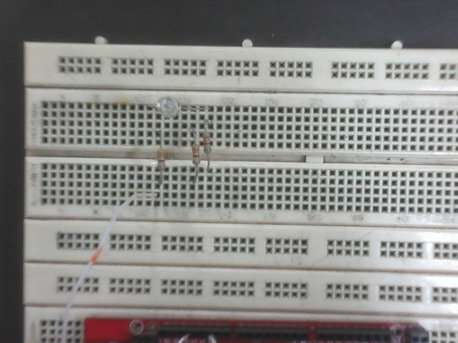
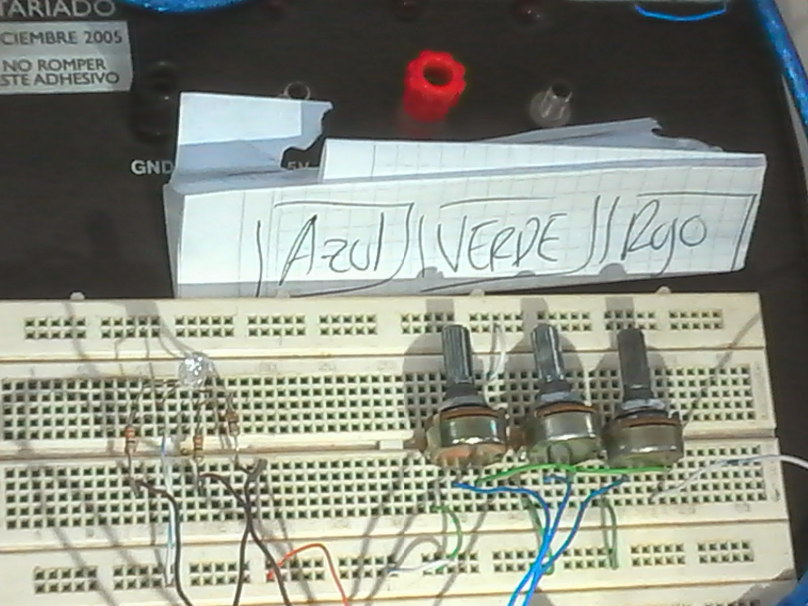
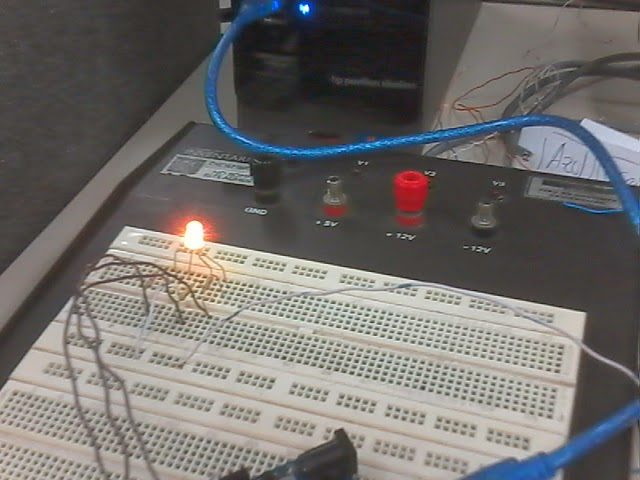
Controlaré a través de Arduino un LED RGB puesto en una protoboard, vía PWM con tres (3) potenciómetros, uno para cada color.
MATERIALES UTILIZADOS
(1) Protoboard
(1) Led
Cable utp
(1) Arduino uno
(3) Potenciometros

DIAGRAMA DEL MONTAJE EN LA PROTOBOARD
DIAGRAMA DEL MONTAJE EN EL CIRCUITO
FOTOS DEL MONTAJE
CÓDIGO ARDUINO
- int a,b,c,pot1,pot2,pot3;
- void setup() {
- pinMode(9, OUTPUT);
- pinMode(10, OUTPUT);
- pinMode(11, OUTPUT);
- pinMode(A5, INPUT);
- pinMode(A4, INPUT);
- pinMode(A0, INPUT);
- }
- void loop() {
- pot1=analogRead(A5);
- a=map(pot1,0,1023,0,255);
- pot2=analogRead(A4);
- b=map(pot2,0,1023,0,255);
- pot3=analogRead(A0);
- c=map(pot3,0,1023,0,255);
- analogWrite(9, a);
- analogWrite(10, b);
- analogWrite(11, c);
- }
VIDEO DEL FUNCIONAMIENTO
LABORATORIO 6
DESCRIPCIÓN DEL LABORATORIO :
Controlaré a través de Arduino un LED RGB puesto en una protoboard, vía PWM con una interfaz gráfica en Processing/ControlP5 para controlar el valor de cada color.
DIAGRAMA DEL MONTAJE EN LA PROTOBOARD

DIAGRAMA DEL MONTAJE EN EL CIRCUITO

FOTOS DEL MONTAJE
CÓDIGO ARDUINO
- // Pines usados para el RGB (9-10) todos
- // son salidas digitales PWM (~)
- int Red = 9;
- int Gre = 10;
- int Blu = 11;
- int valor = 0;
- // Ciclo para activar los tres pines como salida
- void setup() {
- pinMode(9, OUTPUT);
- pinMode(10, OUTPUT);
- pinMode(11, OUTPUT);
- //Comunicación serial a 9600bps
- Serial.begin(9600);
- }
- // Recibe la información de manera serial del processing
- // diferenciando la información del color rojo por la letra "R"
- // la información del color verde por la letra "G" y
- // la información del color azul por la letra "B"
- void loop() {
- if (Serial.available()>0) {
- char Color = Serial.read();
- if (Color == 'R'){
- valor = Serial.parseInt();
- analogWrite(Red,valor);
- }
- if (Color == 'G'){
- valor = Serial.parseInt();
- analogWrite(Gre,valor);
- }
- if (Color == 'B'){
- valor = Serial.parseInt();
- analogWrite(Blu,valor);
- }
- }
CÓDIGO PROCESSING
- // Se utiliza las librerias ControlP5 y Serial del Processing
- import controlP5.*;
- import processing.serial.*;
- // Se define la variable cP5 del tipo ControlP5
- ControlP5 cP5;
- // Se le da nombres a los tres Knob y al Serial
- Knob PerRed;
- Knob PerGre;
- Knob PerBlu;
- Serial serial;
- // Se necesitan inicializar el valor de los colores RGB
- // en este caso lo hacemos en 128
- int Red = 128;
- int Gre = 128;
- int Blu = 128;
- // Configuración inicial
- void setup() {
- size(700, 550); //Tamaño de la ventana
- cP5 = new ControlP5(this); //Crea el objeto ControlP5
- // Crea el Knob del color Rojo
- PerRed = cP5.addKnob("R")
- .setRange(0, 255)
- .setValue(86)
- .setPosition(100, 280)
- .setRadius(100)
- .setNumberOfTickMarks(20)
- .setTickMarkLength(8)
- .setLabelVisible(false)
- .setColorForeground(color(255))
- .setColorBackground(color(0))
- .setColorActive(color(255, 0, 0))
- .setDragDirection(Knob.HORIZONTAL)
- ;
- // Crea el Knob del color Verde
- PerGre = cP5.addKnob("G")
- .setRange(0, 255)
- .setValue(128)
- .setPosition(250, 110)
- .setRadius(100)
- .setNumberOfTickMarks(20)
- .setTickMarkLength(8)
- .setLabelVisible(false)
- .setColorForeground(color(255))
- .setColorBackground(color(0))
- .setColorActive(color(0, 255, 0))
- .setDragDirection(Knob.HORIZONTAL)
- ;
- // Crea el Knob del color Azul
- PerBlu = cP5.addKnob("B")
- .setRange(0, 255)
- .setValue(170)
- .setPosition(400, 280)
- .setRadius(100)
- .setNumberOfTickMarks(20)
- .setTickMarkLength(8)
- .setLabelVisible(false)
- .setColorForeground(color(255))
- .setColorBackground(color(0))
- .setColorActive(color(0, 0, 255))
- .setDragDirection(Knob.HORIZONTAL)
- ;
- String puerto = Serial.list()[0];
- serial = new Serial(this, puerto, 9600);
- }
- // Se dibuja cada frame
- void draw() {
- background(0xFF444444); //Color Gris del fondo
- fill(Red, Gre, Blu);
- rect(50, 90, 600, 415);
- fill(0xFF444444);
- rect(55, 95, 590, 405);
- fill(Red, 0, 0);
- ellipse(200, 380, 220, 220);
- fill(0, Gre, 0);
- ellipse(350, 210, 220, 220);
- fill(0, 0, Blu);
- ellipse(500, 380, 220, 220);
- fill(Red, Gre, Blu);
- textFont(createFont("Gill Sans Ultra Bold", 65));
- text("Led RGB", 180, 70);
- fill(Red, 0, 0);
- textSize(30);
- text("Red", 60, 490);
- fill(0, Gre, 0);
- textSize(30);
- text("Green", 445, 135);
- fill(0, 0, Blu);
- textSize(30);
- text("Blue", 350, 490);
- fill(255);
- textSize(25);
- text("Juan Camilo Fernández López", 190, 540);
- }
- // Como se va a actuar cuando ocurra un evento con los Knobs
- void controlEvent(ControlEvent evento) {
- String nombre = evento.getController().getName();
- int valor = int(evento.getController().getValue());
- serial.write(nombre + valor);
- // Guarda el valor en la variable para cada color,
- // cuando se usa cada Knob
- if (nombre == "R") {
- Red = valor;
- }
- if (nombre == "G") {
- Gre = valor;
- }
- if (nombre == "B") {
- Blu = valor;
- }
- }
LABORATORIO 7
DESCRIPCIÓN DEL LABORATORIO :
Controlaré a través de Arduino ocho (8) LEDs puestos en una protoboard, por medio de un IC 74HC595, controlando individualmente vía una interfaz gráfica en Processing/ControlP5 que LED está encendido o apagado.
DIAGRAMA DEL MONTAJE EN EL CIRCUITO
CÓDIGO ARDUINO
- // Se definen la cantidad de pines que vamos a usar como PIN
- // y la entrada analoga A0 como la que se va a usar por el
- // potenciómetro
- #define PIN 3
- #define Pot A0
- // Se le dan nombres a los pines (7-9) del arduino
- // que van a ser usados por el integrado respectivamente
- // además el pin SH_CP osea Clock debe ser PWM(~)
- const int Latch = 8;
- const int Clock = 9;
- const int Data = 7;
- int led[PIN] = {
- 7,8,9};
- // Ocho secuencias
- int Serie1[7]={
- 129,66,36,24,24,36,66};
- int Serie2[9]={
- 0,128,192,224,240,248,252,254,255};
- int Serie3[12]={
- 255,126,60,24,16,8,16,8,24,60,126,255};
- int Serie4[2]={
- 240,15};
- int Serie5[14]={
- 129,0,131,133,137,145,161,0,193,161,145,137,133,131};
- int Serie6[2]={
- 195,60};
- int Serie7[11]={
- 1,0,1,0,15,0,15,0,255,255,0};
- int Serie8[50]={
- 1,2,4,8,16,32,64,128,64,32,16,8,4,2,1,2,4,8,16,32,64,128,192,160,144,136,132,130,129,131,133,137,145,161,193,225,209,201,197,195,199,203,211,227,243,235,231,239,255,0};
- // Ciclo para activar los tres pines como salida
- // y el pin A0 como entrada
- void setup() {
- for (int i=0; i<PIN; i++){
- pinMode(led[i], OUTPUT);
- }
- pinMode(Pot, INPUT);
- }
- // Recibe la info de la posición del potenciómetro
- void loop()
- {
- int Pos = analogRead(Pot);
- Pos = map(Pos, 0, 1023, 0,7);
- Casos(Pos);
- }
- // Según la posición del potenciómetro escoge un caso
- void Casos(int Valor)
- {
- switch(Valor)
- {
- case 0:
- for(int j=0;j<7;j++)
- {
- On(Serie1[j]);
- }
- break;
- case 1:
- for(int j=0;j<9;j++)
- {
- On(Serie2[j]);
- }
- break;
- case 2:
- for(int j=0;j<12;j++)
- {
- On(Serie3[j]);
- }
- break;
- case 3:
- for(int j=0;j<2;j++)
- {
- On(Serie4[j]);
- }
- break;
- case 4:
- for(int j=0;j<14;j++)
- {
- On(Serie5[j]);
- }
- break;
- case 5:
- for(int j=0;j<2;j++)
- {
- On(Serie6[j]);
- }
- break;
- case 6:
- for(int j=0;j<11;j++)
- {
- On(Serie7[j]);
- }
- break;
- case 7:
- for(int j=0;j<50;j++)
- {
- On(Serie8[j]);
- }
- break;
- }
- }
- // Función para enviar los datos al Integrado IC 74HC595
- void On(int Valor)
- {
- digitalWrite(Latch, LOW);
- shiftOut(Data, Clock, MSBFIRST, Valor);
- digitalWrite(Latch, HIGH);
- delay(100);
- }
CODIGO PROCESSING
/ Se utiliza las librerias ControlP5 y Serial del Processing
import controlP5.*;
import processing.serial.*;
// Se define la variable cP5 del tipo ControlP5
ControlP5 cP5;
// Se le da nombres al Serial
Serial serial;
int[] led = new int[] {
0, 0, 0, 0, 0, 0, 0, 0
};
// Configuración inicial
void setup() {
size(590, 250); //Tamaño de la ventana
noStroke();
cP5 = new ControlP5(this); //Crea el objeto ControlP5
// Crea el Knob del color Rojo
for (int i=0; i<led.length; i++)
{
cP5.addToggle("led"+i, 35+i*70, 140, 30, 30)
.setMode(ControlP5.SWITCH);
}
String puerto = Serial.list()[0];
//Comunicación serial a 9600bps
serial = new Serial(this, puerto, 9600);
}
// Cada uno de los circuilos hecho toma el color determinado
// del Led que se tiene en la protoboard
void draw() {
background(0xFF444444);
fill(led[0] == 0 ? 0xFF222222 : color(255, 255, 0));
ellipse(50, 100, 50, 50);
for (int i=1; i<4; i++) {
fill(led[i] == 0 ? 0xFF222222 : color(255, 0, 0));
ellipse(50+i*70, 100, 50, 50);
}
for (int i=4; i<led.length; i++) {
fill(led[i] == 0 ? 0xFF222222 : color(0, 255, 0));
ellipse(50+i*70, 100, 50, 50);
}
fill(255);
textFont(createFont("Gill Sans Ultra Bold", 50));
text("Enciende un LED", 40, 50);
fill(255);
textSize(25);
text("Juan Camilo Fernández López", 120, 230);
}
// Como se va a actuar cuando ocurra un evento con los botones
void controlEvent(ControlEvent evento) {
String nombre = evento.getController().getName();
int valor = int(evento.getController().getValue());
// Guarda el valor de cada boton
for (int i=0; i<led.length; i++) {
if (nombre.equals("led"+i)) {
led[i] = valor;
serial.write(i);
serial.write(valor);
println("evento: " + i + " / valor: "+valor);
}
}
}
VÍDEO DEL FUNCIONAMIENTO
LABORATORIO 8
DESCRIPCIÓN DEL LABORATORIO :
Controlaré a través de Arduino un Display LED de 7-Segmentos puestos en una protoboard, por medio de un IC 74HC595, para mostrar un número de 0 a 9, dependiendo de la posición del Potenciómetro.
(1) Display LED de 7-Segmentos
(3) potenciometros
DIAGRAMA DEL MONTAJE EN LA PROTOBOARD
DIAGRAMA DEL MONTAJE EN EL CIRCUITO
CÓDIGO ARDUINO
- // Se definen la cantidad de pines que vamos a usar como PIN
- // y la entrada analoga A0 como la que se va a usar por el
- // potenciómetro
- #define PIN 3
- #define Pot A0
- // Se le dan nombres a los pines (7-9) del arduino
- // que van a ser usados por el integrado respectivamente
- // además el pin SH_CP osea Clock debe ser PWM(~)
- const int Latch = 8;
- const int Clock = 9;
- const int Data = 7;
- int led[PIN] = {
- 7,8,9};
- // El valor de cada uno de los numeros que voy
- // a mostrar en mi Display
- int Numeros[10]={63,6,91,79,102,109,125,7,127,111};
- // Ciclo para activar los ocho pines como salida
- // y el pin A0 como entrada
- void setup() {
- for (int i=0; i<PIN; i++){
- pinMode(led[i], OUTPUT);
- }
- pinMode(Pot, INPUT);
- }
- // Recibe la info de la posición del potenciómetro
- void loop()
- {
- int Pos = analogRead(Pot);
- Pos = map(Pos, 0, 1023, 0,9);
- Casos(Pos);
- }
- // Según la posición del potenciómetro escoge un caso
- // osea un numero
- void Casos(int Valor)
- {
- switch(Valor)
- {
- case 0:
- On(Numeros[0]);
- break;
- case 1:
- On(Numeros[1]);
- break;
- case 2:
- On(Numeros[2]);
- break;
- case 3:
- On(Numeros[3]);
- break;
- case 4:
- On(Numeros[4]);
- break;
- case 5:
- On(Numeros[5]);
- break;
- case 6:
- On(Numeros[6]);
- break;
- case 7:
- On(Numeros[7]);
- break;
- case 8:
- On(Numeros[8]);
- break;
- case 9:
- On(Numeros[9]);
- break;
- }
- }
- // Función para enviar los datos al Integrado IC 74HC595
- void On(int Valor)
- {
- digitalWrite(Latch, LOW);
- shiftOut(Data, Clock, MSBFIRST, Valor);
- digitalWrite(Latch, HIGH);
- delay(10);
VÍDEO DEL FUNCIONAMIENTO


.jpg)


